

Views: 0 Author: Site Editor Publish Time: 2026-09-30 Origin: Site


Achieving maximum settling capacity within a limited physical footprint is a core challenge in wastewater engineering. System designers are tasked with efficiently separating suspended solids without triggering sludge blinding or hydraulic bottlenecks. Choosing the wrong plate angle in a Lamella Clarifier can quickly lead to system failure in two primary ways. If the angle is too shallow, sludge builds up rapidly, clogging channels and risking structural damage. On the other hand, excessively steep angles reduce the effective projected surface area, forcing engineers to design oversized tanks that inflate both capital costs and facility space requirements.
Selecting the ideal plate inclination demands a rigorous evaluation process. Engineers generally focus on angles between 45° and 65°. The final choice relies heavily on influent characteristics, solid density, and the exact design of the clarification system. By carefully aligning the plate angle with the specific gravity and rheology of the target solids, operators can significantly enhance settled water quality and achieve stable, low-maintenance operations.
Optimal Angle Range: Industry research and field data confirm that an inclination between 45° and 65° strikes the best balance between efficient solid settling and smooth sludge sliding.
The Surface Area Trade-off: While shallower angles boost the effective projected surface area (thereby shrinking the required footprint), they also raise the risk of solids sticking to the plates.
Influent Dependency: The optimal angle is ultimately driven by the physical properties of the solids. Heavy, granular particles perform well with shallower angles, whereas sticky biological matter or pin-floc demands steeper inclines (60° and above).
Design Variations Matter: Selecting between flat parallel plates and chevron or tube settler lamella clarifier configurations heavily influences sludge accumulation behavior, coalescence rates, and overall maintenance needs.
Inclined plate sedimentation is rooted in Hazen's theory, which states that a basin's settling efficiency is governed by its surface area rather than its overall depth. By angling the plates, designers significantly shorten the vertical distance a suspended particle must travel before it encounters a solid surface. In a traditional open-span clarifier, a particle may have to sink ten to fifteen feet to reach the sludge zone—a process that could take hours depending on the floc's specific gravity. However, inside an Inclined plate clarifier, that identical particle only drops a few inches before resting on the lower plate. Once it makes contact, the system essentially removes it from the active flow. This clever geometric arrangement multiplies the functional settling area, enabling facilities to process massive flow rates within a remarkably compact footprint.
Field operators witness these physics firsthand every day. As wastewater enters the plate pack, fluid velocity decreases and laminar flow conditions take over. With Reynolds numbers in these narrow channels generally remaining well below 500, the upward movement of water is remarkably smooth and non-turbulent. This stable environment lets gravity effectively dictate the particle's path, pulling it out of suspension with impressive speed.
The physical surface of the plates naturally promotes particle agglomeration. As wastewater travels upward through the tight channels, suspended solids fall out of the main flow and land on the upper face of the plate beneath them. This action generates a localized zone of highly concentrated solids. The subsequent coalescence process unfolds in a clear, predictable sequence:
Initial Contact: Micro-flocs and suspended particles escape the upward fluid velocity and make direct physical contact with the inclined plate.
Agglomeration: As more particles gather on the surface, gravity pulls them downward. Along this descent, smaller particles bump into and fuse with larger masses.
Density Increase: This continuous rolling and sliding action gently compresses the flocs, forcing out trapped water and creating denser, more robust precipitates.
Rapid Descent: These heavy, consolidated masses easily overcome any remaining upward fluid drag, plunging rapidly into the sludge hopper at the unit's base.
Efficient particle removal hinges on a precise mathematical balance between fluid dynamics and physics. A suspended particle will only settle successfully if its downward settling velocity—divided by the vertical channel height—is greater than the upward velocity of the fluid. If the upward flow is too intense, the resulting drag forces will simply sweep the particles up and out through the effluent launders, ruining the clarity of the treated water.
Engineers carefully manage this dynamic by fine-tuning both plate spacing and installation angle. While tighter spacing minimizes the distance a particle must drop, it simultaneously accelerates the upward fluid velocity for any given flow rate. Striking the right balance ensures that solids make contact with the plate surface long before the water escapes the top of the channel. Practically speaking, if a facility encounters sudden surges in flow, the corresponding spike in upward velocity frequently causes temporary solid carryover until conditions stabilize.
Determining the effective settling area directly dictates the physical dimensions of the clarifier tank. The projected surface area is calculated by multiplying the actual physical plate area by the cosine of the installation angle. This strict mathematical formula illustrates why steeper angles naturally result in a smaller projected area. Engineers must meticulously weigh this trade-off, knowing that steeper angles demand a substantially higher number of physical plates to maintain the same overall treatment capacity.
Installation Angle | Cosine Multiplier | Actual Plate Area | Effective Projected Area | Primary Application |
|---|---|---|---|---|
45 Degrees | 0.707 | 1000 sq. ft. | 707 sq. ft. | Heavy grit, sand, mining slurries |
50 Degrees | 0.642 | 1000 sq. ft. | 642 sq. ft. | Dense metal hydroxides |
55 Degrees | 0.573 | 1000 sq. ft. | 573 sq. ft. | Standard industrial precipitates |
60 Degrees | 0.500 | 1000 sq. ft. | 500 sq. ft. | Municipal wastewater, mixed flocs |
65 Degrees | 0.422 | 1000 sq. ft. | 422 sq. ft. | Sticky biological sludge, pin-floc |
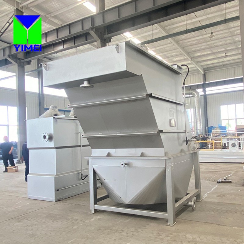
Designing a system in the 45° to 55° range maximizes projected surface area, offering outstanding footprint reduction. However, this shallow incline is strictly reserved for heavy, dense, and non-cohesive inorganic solids. Common applications involve sand, grit, mill scale, and heavy metal precipitates typical of mining or metal finishing environments. Because these materials feature a high specific gravity (frequently above 2.5), they can slide downward effortlessly, even on gentle slopes.
The major drawback here is an elevated risk of sludge blinding. Plant operators frequently discover that while a 45-degree angle looks flawless on paper for metal hydroxides, a slight drift in upstream pH can turn the floc gelatinous, causing the clarifier to blind over completely in just a matter of hours. Should the influent characteristics shift and the solids turn sticky, they simply will not slide. Preventing catastrophic plate blockage in these setups demands rigorous upstream pre-screening, exact chemical dosing, and consistently predictable influent conditions.
A 60-degree angle represents the gold standard across the water treatment industry. With a cosine of 0.5, this angle perfectly balances generous projected surface area with a sufficiently steep incline. At 60 degrees, gravitational pull provides enough downward force to overcome the static friction of most mixed-density flocs, which generally carry a specific gravity ranging from 1.05 to 1.2.
Municipal wastewater treatment plants and conventional industrial facilities overwhelmingly favor this angle for reliable, gravity-driven sludge removal. It easily accommodates minor fluctuations in influent chemistry and solid loading without demanding emergency manual cleaning. For most design engineers, 60 degrees remains the safest and most logical baseline when precise sludge rheology data isn't available during early planning stages. It grants a comfortable operational safety margin, even if upstream coagulation processes experience brief hiccups.
Angles of 65 degrees and above prioritize aggressive sludge removal over sheer surface area. This ultra-steep configuration is virtually mandatory when dealing with sticky biological solids or extremely light pin-floc that stubbornly resists sliding. Biological sludge—such as activated sludge carryover—features a specific gravity that hovers remarkably close to water (roughly 1.01) and possesses a frustrating tendency to cling to surfaces and bridge narrow channel gaps.
A steeper plate angle magnifies the gravitational shear force, compelling these difficult solids down into the sludge hopper. Naturally, the primary trade-off is a sharp decrease in projected settling area. To hit the required treatment capacity, the system's physical footprint must grow, often requiring a taller tank design. While this certainly drives up initial capital expenditure, facility managers are usually willing to absorb the upfront cost. Ultimately, this approach slashes long-term operational expenses by minimizing costly confined-space manual cleanings and preventing unexpected process downtime.
Internal architecture fundamentally dictates how both water and solids behave inside the clarification zone. Traditional flat, parallel inclined plate clarifiers rely on smooth, continuous sheets of material, most often fabricated from stainless steel or fiberglass-reinforced plastic (FRP). These sturdy plates span the entire length of the settling zone without any lateral roadblocks. In stark contrast, a Tube settler lamella clarifier utilizes a honeycomb or chevron-shaped matrix. Manufacturers generally extrude these tubes from lightweight PVC, fusing them into rigid block structures. While the tube design forms completely enclosed geometric channels, the parallel plate approach provides open, continuous slots. This distinct structural contrast dramatically changes fluid distribution patterns and solid settling trajectories.
Sludge accumulation behaves completely differently depending on the chosen design. Parallel plates provide a clear, unobstructed path downward. Once solids coalesce on a flat surface, they slide straight into the collection hopper without encountering structural roadblocks. While chevron-shaped lamella designs and complex tube configurations are highly effective at packing maximum surface area into a tight volume, the inherently enclosed nature of tube settlers inevitably introduces restrictive pinch points.
The corners and structural intersections inside a honeycomb matrix act as anchor points, encouraging sticky solids to bridge the gaps. Over time, this bridging creates stubborn localized clogging. Worse yet, once a single tube blocks entirely, the upward fluid velocity in neighboring tubes immediately surges, potentially triggering a cascading failure of solid carryover. Flat parallel plates completely eliminate these lateral anchor points, making them a vastly superior choice for scenarios involving high solids loading or extremely cohesive sludge.
Long-term operational success is heavily tied to how easily a system can be cleaned. Tube settlers are undeniably efficient and lightweight, which contractors love during installation. Unfortunately, their somewhat fragile PVC construction severely limits maintenance options. Operators are typically prohibited from using high-pressure washers or aggressive mechanical scraping tools, as these can quickly destroy the delicate honeycomb matrix. If a tube settler block becomes fully clogged, the entrapped sludge can weigh thousands of pounds. Simply attempting to lift a heavily blinded block out of the tank frequently shreds the plastic structure.
Conversely, rigid inclined plates easily endure aggressive mechanical cleaning protocols. Thick FRP or durable stainless steel plates give operators the freedom to drain the tank and quickly drop a high-pressure wash wand straight down the open channels. Especially in heavy industrial settings with highly unpredictable solid loads, the rugged durability of flat plates guarantees superior mechanical reliability and significantly lower lifecycle maintenance costs.
Feature | Flat Parallel Plates (FRP/Stainless) | Tube Settlers (PVC Honeycomb) |
|---|---|---|
Lateral Obstructions | None (Open channels) | High (Enclosed corners) |
Clogging Risk | Low to Moderate | High (Prone to bridging) |
Cleaning Method | High-pressure wash, mechanical scraping | Low-pressure rinse only |
Structural Integrity | High (Supports heavy sludge loads) | Low (Can collapse if fully blinded) |
Installation Weight | Heavy (Requires crane for large packs) | Lightweight (Easy manual handling) |
Upstream chemical treatment fundamentally changes the physical makeup of suspended solids. Introducing coagulants—such as aluminum sulfate or ferric chloride—neutralizes repelling electrical charges on particles, while polymer flocculants effectively weave these neutralized bits into larger, heavier clumps. When paired with perfectly optimized plate angles, this process dramatically boosts settled water quality by creating a highly efficient, tranquil settling zone tailored specifically for these chemically modified flocs.
When operators pinpoint the exact chemical dosing, the resulting flocs become dense and highly shear-resistant. This enables the facility to deliver crystal-clear effluent, even at a standard 60-degree incline. Interestingly, the inherent efficiency of the plates often allows plants to modestly scale back their coagulant dosing. Because the tight channels physically force particles to collide, the mechanical design supplements chemical agglomeration, actively driving down overall chemical consumption. To maintain this delicate balance, field technicians rely on daily jar testing, tweaking feed rates to ensure the resulting floc perfectly matches the clarifier's physical geometry.
Physical clarifier dimensions directly establish the hydraulic retention time within the crucial laminar flow zone. As a general industry rule, optimal pin-floc removal requires a plate length of at least six feet. This generous length guarantees that particles have more than enough time to settle securely onto the plate surface before the water spills over the upper effluent weir. Designs utilizing shorter plates frequently battle carryover issues, simply because the particles run out of time to escape the fluid stream.
Furthermore, plate spacing must be carefully evaluated in conjunction with the selected installation angle. Standard channel spacing usually falls between 1 and 2 inches. While a tighter gap undeniably boosts total surface area, it simultaneously accelerates the upward fluid velocity. Push the plates too close together, and sticky solids will inevitably bridge the gap, leading to immediate and catastrophic blinding. Engineers must masterfully balance plate length and spacing against the floc's specific gravity, maximizing available settling area while proactively preventing any chance of bridging.
The Hydraulic Loading Rate (HLR) remains the single most critical metric for gauging clarifier performance. Calculated by dividing the total influent flow by the total projected surface area, HLR is generally expressed in gallons per minute per square foot (gpm/ft⊃2;). Because the specified plate angle directly dictates that projected area, it fundamentally establishes the system's absolute maximum allowable HLR.
If a facility pushes flow rates beyond the designed HLR, the sheer force of the upward fluid velocity will effortlessly overpower the particles' natural downward settling velocity. This imbalance triggers immediate solid carryover, decimating effluent clarity. To mitigate this risk, engineers establish a highly conservative HLR, deliberately basing their calculations on the absolute lightest expected particles within the waste stream. By strictly enforcing this HLR limit, operators ensure their clarifier delivers unwavering performance, even when slammed with peak flow events.
Heavy Metal Hydroxides: Typical HLR of 0.2 to 0.3 gpm/ft⊃2;
Standard Municipal Wastewater: Typical HLR of 0.4 to 0.6 gpm/ft⊃2;
Sand and Heavy Grit: Typical HLR of 0.8 to 1.2 gpm/ft⊃2;
It is important to note that even a mathematically flawless plate angle will fail miserably if the incoming flow isn't distributed evenly across the entire plate pack. Short-circuiting happens when water seeks the path of least resistance, violently funneling the bulk of the flow through an isolated section of the clarifier. This localized spike in velocity aggressively rips previously settled solids right off the plates, flushing them directly into the clean effluent, all while the rest of the plate pack sits completely underutilized.
Specify precision-engineered influent distribution manifolds designed to introduce water uniformly across the entire base of the plate pack.
Install well-designed effluent collection launders equipped with fully adjustable v-notch weirs across the top of the unit.
Use a precision laser level during commissioning to ensure the weirs are perfectly flat, guaranteeing identical water draw across every individual channel.
Incorporate strategic baffle walls within the transition zone to effectively kill influent velocity and stop turbulent eddies from violently entering the settling zone.
Catastrophic structural failure is a very real threat if heavy sludge accumulation surpasses the mechanical limits of the internal framework. When a plate angle is far too shallow for a particular sludge profile, solids simply refuse to slide. As the thick sludge builds up over time, its weight multiplies exponentially. In extreme worst-case scenarios, this massive static load can warp heavy plates, snap robust support brackets, or trigger a total, devastating collapse of the internal matrix.
Carefully select construction materials tailored to the specific application environment. Specify 304 or 316 Stainless Steel for high-temperature, highly corrosive Industrial lamella clarifier setups.
Utilize heavy-duty, reinforced FRP for standard municipal installations where overall weight reduction and excellent corrosion resistance are top priorities.
Always demand comprehensive structural load calculations from the equipment manufacturer, verifying that the support frame can comfortably hold the colossal weight of a fully blinded, water-logged plate pack.
Install reliable sludge-level monitoring sensors deep in the hopper to automatically trigger blowdown valves long before accumulated sludge can back up into the active plate zone.
Conduct rigorous bench-scale jar testing to definitively lock in the settling velocity and specific gravity of the target floc well before finalizing equipment dimensions.
Request sophisticated computational fluid dynamics (CFD) modeling from shortlisted manufacturers to visually guarantee uniform flow distribution across the proposed plate pack.
Launch comprehensive on-site pilot testing for highly complex or wildly variable industrial wastewater streams, proving that the selected plate angle actually performs under real-world conditions.
Carefully evaluate the necessary mechanical cleaning routines and structural load limits of the chosen plate materials, ensuring they align perfectly with your site's existing maintenance capabilities.
A: The widely accepted industry baseline is 60 degrees. This specific angle strikes an excellent balance—offering ample projected surface area for efficient settling while remaining steep enough to let mixed-density sludge slide reliably into the hopper without requiring manual intervention.
A: Projected area is calculated by taking the physical area of the plates and multiplying it by the cosine of the installation angle. Because steeper angles yield smaller cosines, they inherently provide less effective projected settling area per square foot of material, which means you'll need a larger tank to process the same flow rate.
A: As wastewater rises, solids naturally drop onto the surface of the lower plate. Gravity then pulls these particles down the incline. During this gentle sliding motion, smaller particles continuously bump into one another and bind together, creating much larger, heavier flocs that can easily overpower upward fluid drag and settle quickly.
A: Inclined plate clarifiers rely on flat, parallel sheets that feature open, unobstructed lateral channels, virtually eliminating the risk of sludge bridging. Tube settlers, conversely, utilize enclosed chevron or honeycomb structures. While tubes expertly maximize surface area, their enclosed corners create restrictive pinch points where sticky solids frequently accumulate and cause severe blockages.
A: In almost all cases, no. The plate angle is a highly integrated, fixed structural component that is either welded or bolted securely into the tank's main framework. Altering the angle would require completely tearing out and rebuilding the internal support matrix, fabricating brand-new brackets, and replacing the entire plate pack assembly.
A: You can proactively prevent buildup by specifying the correct angle (60° or steeper for sticky or biological solids), fine-tuning upstream coagulant chemistry to produce dense, heavy flocs, ensuring flawlessly uniform flow distribution across the tank, and running a strictly automated sludge blowdown schedule to ensure the bottom hopper never overflows.


