

Views: 0 Author: Site Editor Publish Time: 2026-09-23 Origin: Site


True wastewater treatment efficiency is driven far more by microscopic fluid dynamics than by simple tank volume or retention time. In any operational facility, the physical mechanics of particle-bubble agglomeration ultimately determine system performance. When flotation is sub-optimal, facilities face steep financial and operational consequences, including regulatory permit violations and excessive chemical usage. Consequently, the treatment efficiency within a Dissolved Air Flotation Machine can vary wildly—from a mere 25% up to an impressive 99%. This significant performance gap hinges almost entirely on the precise bubble generation conditions and fluid dynamics active in the contact zone.
When undertaking capital investments or plant upgrades, facility managers must carefully evaluate the underlying bubble generation technology. Rather than merely looking at basic tank dimensions, prospective buyers should focus intently on saturator mechanics. Ultimately, bubble size acts as the chief driver of separation efficiency, directly influencing chemical dosing needs and overall regulatory compliance. It is this precision in bubble control that truly sets a standard, adequate setup apart from a high-performance installation.
Optimal Dimensions: Microbubbles—typically measuring ≤50 µm—are essential for maximizing the surface-area-to-volume ratio, which guarantees the best possible adhesion to suspended solids and oils.
Pressure Dynamics: Both the operating pressure and the engineering of the pressure release mechanism directly govern bubble nucleation, size distribution, and the total volume of air precipitated.
OPEX Reduction: Highly precise bubble generation minimizes the need for chemical coagulants and flocculants, thereby slashing ongoing operational expenses and sludge disposal fees.
Application Specificity: Because distinct contaminant profiles (such as heavy metals versus FOG) demand specific air-to-solids (A/S) ratios, precise bubble size control remains a crucial metric when evaluating any industrial DAF system.
The entire flotation process relies on successful particle-bubble collisions. These rapid physical interactions take place inside the vessel's contact zone, right where the recycled white water mixes with the raw influent. To achieve effective separation, suspended solids and oil droplets must physically intercept the rising air bubbles. Proper adhesion depends on both favorable surface chemistry and sufficient contact time. By offering an exponentially larger total surface area for a specific volume of dissolved air, smaller bubbles fundamentally reshape the geometry of this interaction. This vastly expanded surface area greatly boosts the likelihood of trapping suspended particles before they can escape the contact zone.
Applying the mathematics of spherical geometry to fluid dynamics reveals a striking advantage: halving a bubble's diameter effectively doubles its available surface area for the exact same volume of injected air. The resulting dense cloud of microbubbles acts like a fine, tightly woven net rising steadily through the incoming wastewater stream. It becomes incredibly difficult for particles to slip through such a concentrated wall of air. Naturally, this higher collision frequency leads directly to much better overall removal efficiency. On the plant floor, operators can visually confirm this optimal condition when the white water takes on a smooth, milky appearance, rather than looking like a violently boiling froth.
Bubble Diameter (µm) | Relative Surface Area Multiplier | Collision Probability | Visual Appearance in Contact Zone |
|---|---|---|---|
1000 (Macro-bubble) | 1x | Very Low | Clear water with large, fast-rising bubbles |
100 (Fine bubble) | 10x | Moderate | Translucent, fizzy appearance |
50 (Microbubble) | 20x | High | Opaque, milky white water |
20 (Ultra-fine bubble) | 50x | Maximum | Dense, thick white cloud with slow rise |
A bubble's diameter has a direct impact on its rise velocity. This relationship is defined by Stokes' Law, which notes that a sphere's terminal velocity as it rises through a fluid is proportional to the square of its radius. Consequently, larger bubbles shoot up quickly through the water column, whereas smaller bubbles float upward at a much slower, controlled pace. For flotation to succeed, a crucial density shift is required: the combined mass of the particle and the bubble must become less dense than the surrounding water. Once it crosses this physical threshold, the agglomerated mass readily floats to the surface.
When designing an injection manifold, engineers face a delicate balancing act. Bubbles simply cannot be too large or too small. Oversized bubbles rise so rapidly that they induce violent turbulence, which can tear apart fragile floc structures well before they ever reach the surface layer. On the flip side, extremely tiny bubbles (measuring under 10 µm) often lack the necessary buoyancy to lift exceptionally dense, heavy particle masses like metal hydroxides. Therefore, an optimally designed system hones in on a very specific bubble size range—providing just enough lift without triggering destructive shear forces.
Verify that the influent flow rate matches the design capacity to prevent any hydraulic washout of the bubble cloud.
Inspect the contact zone closely for signs of boiling or large bubble breakthrough, which often indicates coalescing air.
Measure the rise rate of the floc structure; ideally, it should drift steadily upward without breaking apart.
Adjust the recycle flow percentage to carefully increase or decrease the total volume of air delivered into the contact zone.
Guided by industry-standard engineering principles, experts have established a strict, optimal range for flotation mechanics. For wastewater treatment to be truly effective, microbubbles must fall between 10 µm and 50 µm. Within this specific threshold, bubbles demonstrate the ideal physical behavior required for solid-liquid separation. They ascend slowly enough to maximize their contact time with contaminants, yet still possess ample buoyancy to lift agglomerated flocs. Ultimately, this specific size bracket is the mechanical sweet spot for achieving an impressive 99% removal of total suspended solids (TSS).
Microbubbles within this ideal range naturally form a highly stable, tightly concentrated float layer at the top of the tank. Rather than bursting violently at the surface, they accumulate smoothly. This inherent stability prevents the creation of a turbulent, frothy layer that could easily cause contaminants to drop back down into the clarified effluent. Furthermore, a stable float layer empowers mechanical skimmer flights to sweep away sludge efficiently, without forcing solids back into the water column. By strictly maintaining the ≤50 µm threshold, facilities can guarantee consistent and reliable effluent quality, even when shift loads fluctuate.
Chemical coagulants, such as polyaluminum chloride (PAC) or ferric sulfate, work by neutralizing the negative electrical charges found on suspended particles. Following this, flocculants—typically high-molecular-weight polymers—bind these neutralized particles together to form larger, visible masses. Interestingly, bubble size has a direct impact on the precise amount of chemical dosing needed to successfully achieve separation. When microbubble generation is highly efficient, it effectively compensates for smaller floc sizes. Because dense microbubble clouds are perfectly capable of lifting tiny, pinpoint flocs, operators no longer need to rely on massive, heavy floc structures just to achieve the necessary buoyancy.
For plant managers, this dynamic yields incredibly favorable operational outcomes. By simply optimizing saturator performance, facilities can drastically cut down on their chemical dosing requirements. Naturally, using fewer chemicals directly boosts the equipment's return on investment while simultaneously reducing the chemical toxicity of the resulting sludge. Moreover, a reduction in chemical volume translates into lower sludge disposal costs and significantly drier filter press cakes downstream. In this way, precision bubble generation turns what would have been hefty chemical expenditures into substantial, long-term operational savings.
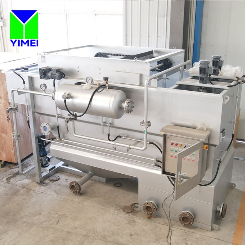
Within the recycle stream, air dissolution takes place under intensely high pressure. To hit maximum saturation, most systems operate efficiently between 4 and 6 bar (roughly 58 to 87 psi). This physical dissolution process is dictated by Henry's Law, which states that the amount of dissolved gas present in a liquid is directly proportional to its partial pressure just above that liquid. Consequently, higher pressure forces a greater number of air molecules into the liquid phase, resulting in a highly supersaturated solution perfectly primed for precipitation.
The system's discharge pressure correlates directly with the final size of the bubbles. In practice, higher transfer pressures result in a remarkably smaller bubble diameter. At the exact same time, the sheer volume of bubbles increases exponentially as they are released through the pressure reduction valve. Ultimately, this intricate pressure dynamic functions as the true engine driving the flotation process. By maintaining a consistent pressure, operators can guarantee a steady, reliable supply of perfectly sized microbubbles. Conversely, any pressure fluctuations—whether caused by failing pumps or severely clogged strainers—will instantly degrade the quality of the bubble cloud, causing a rapid deterioration in effluent quality.
Operating Pressure (Bar) | Air Solubility (g/m³) | Average Bubble Size (µm) | System Performance Impact |
|---|---|---|---|
2.0 - 3.0 | Low | 70 - 100 | Poor lift, high shear, frequent drop-out |
4.0 - 5.0 | Optimal | 30 - 50 | Stable float, excellent clarity, low chemical use |
5.5 - 6.5 | Maximum | 15 - 30 | Dense sludge blanket, ideal for heavy FOG |
> 7.0 | Diminishing Returns | < 15 | Excessive pump wear, potential blinding of flocs |
Vital mechanical components govern the critical nucleation phase, where dissolved air formally transitions back into a gas. Serving as the primary generation point, the pressure release valve plays a central role. The moment pressure drops across the valve orifice, air immediately precipitates as a flurry of small bubbles. These bubbles then rise uniformly throughout the vessel to make contact with the raw influent. Crucially, the physical design of this release mechanism is what dictates the initial bubble size. If a valve suffers from poor design or excessive wear, it often leads to immediate bubble coalescence right at the critical injection point.
Depending on the specific application, engineers may deploy a variety of pressure release mechanisms. While needle valves provide excellent adjustable control, they do demand frequent, manual fine-tuning by plant operators. Alternatively, specialized nozzles deliver highly precise, fixed-orifice pressure drops, greatly reducing the need for daily intervention. More advanced nozzle designs go a step further, actively preventing premature bubble coalescence by sustaining high fluid velocities right up until the stream enters the open contact zone. Carefully evaluating these mechanical components is an absolute necessity to ensure long-term system reliability and consistently high effluent quality.
Tackling emulsified oils introduces a set of highly unique physical challenges in industrial wastewater management. Emulsions are made up of microscopic oil droplets that remain tightly suspended in water, frequently stabilized by surfactants or intense mechanical shearing. While free-floating oils can be separated with relative ease using gravity in a standard API separator, emulsified oils demand active, targeted intervention to successfully break the suspension. Consequently, a specialized Oil water separation machine must rely heavily on advanced microbubble technology, primarily because traditional gravity separators simply cannot reach the stringent removal rates required for safe discharge compliance.
For this specific application, generating a high density of ultra-fine microbubbles is absolutely essential. These tiny bubbles must successfully attach themselves to low-density oil droplets, all while taking care not to shatter the delicate chemical bonds previously formed by the coagulant. Essentially, the process demands a very gentle buoyancy to softly lift the oil upward to the surface. In contrast, large bubbles introduce violent shear forces into the water column, which can easily sever these fragile oil-bubble connections and plunge the oil right back into the emulsion. Microbubbles, however, supply exactly the right amount of lift without ever disrupting the delicate separation dynamics.
Facilities such as food processing plants, slaughterhouses, and large municipal sites frequently produce incredibly heavy and complex contaminant loads. Their waste streams are notoriously packed with massive concentrations of Fats, Oils, and Grease (FOG), alongside exceptionally high Total Suspended Solids (TSS). To survive, a robust Grease removal dissolved air flotation machine must be engineered to tackle these aggressive profiles head-on, without clogging or suffering systemic failure. The equipment must efficiently lift heavy, stubbornly sticky grease masses, all while expertly managing the sudden, massive spikes in loading that occur during intense plant washdown cycles.
When dealing with grease, bubble size has a profound impact on the structural integrity of the resulting float layer. Because microbubbles embed themselves deeply within the dense grease matrix, they provide a highly uniform, stable buoyancy across the entire surface. This crucial stability prevents massive, heavy grease clumps from suddenly dropping out of the float and plunging to the bottom of the tank. Such drop-outs are disastrous, as they severely contaminate the clarified effluent below and quickly overload the bottom auger system. Thankfully, consistent microbubble generation ensures that the top grease layer remains thick, remarkably dry, and exceptionally easy for the top flights to skim away.
It is quite common for flotation units to be deployed as waste activated sludge (WAS) thickeners within biological treatment plants. However, sludge thickening demands vastly different operational parameters compared to standard primary clarification. Here, the primary objective shifts away from simply producing clean water, focusing instead on maximizing the dry solids concentration of the floated material. During this vital dewatering step, bubble size plays a truly pivotal role. Dense clouds of microbubbles work aggressively to pack sludge particles tightly together at the surface, physically forcing excess water out of the matrix.
By maintaining optimal bubble-to-particle ratios, facilities can routinely achieve notably higher dry solids concentrations. As the sludge blanket rises and steadily compacts against the water's surface, the microbubbles literally squeeze the interstitial water right out of the sludge. This vigorous action results in a significantly thicker and drier floated sludge, frequently hitting 4% to 6% solids content. Naturally, producing a thicker sludge dramatically cuts down on downstream dewatering costs. Equipment like centrifuges, belt presses, and filter presses operate at peak efficiency when supplied with a pre-thickened feed. Therefore, mastering precise bubble control translates directly into substantially lower overall sludge handling and hauling expenditures.
The true processing capacity of a system is largely defined by its Air-to-Solids (A/S) ratio. This critical metric compares the mass of precipitated air delivered via the recycle system against the total mass of influent solids flooding into the tank. It is imperative that you carefully match the manufacturer's advertised capabilities with your site's specific wastewater characterization. To be effective, an Industrial DAF system absolutely must sustain these optimal ratios, even when hit with wildly varying shift loads. If the air volume is insufficient, the treatment process will fail almost immediately, leaving solids to either sink to the bottom or pass harmlessly straight through the weir.
Always take the time to verify a system's performance capabilities across its entire operating spectrum. In industrial environments—especially during intense sanitation shifts—influent loads are known to fluctuate wildly. The installed bubble generation system must be agile enough to scale its air delivery in real-time, whether that is achieved via variable frequency drives (VFDs) linked to the recycle pump or through easily adjustable air rotameters. Importantly, it must preserve the optimal bubble size even when pushed to its maximum hydraulic capacity. To avoid the costly mistake of purchasing an undersized unit, always request hard, empirical data demonstrating the bubble size distribution across a variety of A/S ratios.
When evaluating equipment, energy consumption must always be thoughtfully weighed against the quality of the dissolved air produced. The recirculation pump is the true workhorse of the dissolution process; it pulls in clarified effluent and forcibly drives it under intense pressure straight into the saturator. Be sure to scrutinize the kilowatt (kW) draw of this pivotal component. Modern multiphase pumps, for instance, can dissolve air directly within the pump casing itself, aggressively shearing the air and water mixture right through the impeller. This clever design completely eliminates the need for noisy external air compressors and large, bulky saturator tubes.
Conversely, traditional setups rely heavily on separate air compressors paired with large saturator vessels packed full of media, a design intended to maximize air-water contact. While multiphase pumps undeniably offer a much smaller footprint and significantly simplified maintenance routines, traditional saturators frequently deliver higher total air dissolution rates and possess the robust capacity to handle more extreme operating pressures. During the procurement phase, it is vital to discuss these mechanical trade-offs thoroughly. The technology you ultimately select will profoundly impact not only your daily power consumption but also the long-term consistency of your bubble precipitation.
In many real-world scenarios—especially during complex retrofits or cramped indoor installations—the facility's available footprint dictates the final equipment selection. To combat space constraints, high-rate DAFs leverage highly optimized bubble generation alongside internal lamella plates, drastically reducing necessary retention times. This allows them to process substantially more water within a much smaller physical space. In stark contrast, standard designs demand much larger open tanks to achieve the exact same level of separation, simply because they rely heavily on extended hydraulic retention times. Put simply, exceptional bubble efficiency translates directly into a reduced requirement for tank surface area.
Because highly efficient microbubbles rise with steady precision, they separate contaminants at an incredibly rapid pace. This accelerated separation process allows engineers to utilize smaller tank geometries and noticeably shallower depths. Ultimately, facility managers can save incredibly valuable floor space simply by investing in superior bubble technology, rather than defaulting to purchasing a massive steel tank. Always take the time to compare the hydraulic loading rates across different models to truly grasp their actual footprint efficiency.
System Type | Typical Bubble Size | Retention Time | Hydraulic Loading Rate (gpm/ft²) | Footprint Requirement |
|---|---|---|---|---|
Standard Open Tank DAF | 50 - 100 µm | 20 - 30 minutes | 1.5 - 3.0 | Large |
High-Rate Lamella DAF | 10 - 40 µm | 5 - 15 minutes | 4.0 - 8.0 | Compact |
Multiphase Pump DAF | 20 - 50 µm | 10 - 20 minutes | 3.0 - 5.0 | Very Compact |
Hidden design flaws within the piping network can utterly destroy bubble integrity long before the air ever makes contact with the incoming wastewater. If fluid velocities drop too low, or if the system features sharp 90-degree elbows immediately following the pressure release valve, pristine microbubbles can easily merge into massive macro-bubbles right inside the injection piping. This premature coalescence drastically shrinks the total surface area available for effective separation. To make matters worse, when these macro-bubbles finally enter the main tank, they introduce severe system shear, violently disrupting the contact zone and shattering delicate flocs.
To mitigate these serious risks, buyers must carefully evaluate the system's internal hydraulics during the initial procurement phase. Closely inspect the internal baffling design of any proposed unit, and intensely scrutinize both the injection port geometry and the layout of the recycle manifold. It is critical to ensure that the chosen design promotes a perfectly uniform, low-velocity bubble distribution spanning the entire width of the contact zone. Sound fluid dynamics are the only true defense against bubbles colliding and merging prematurely. For large-scale installations, never hesitate to demand detailed computational fluid dynamics (CFD) models from the manufacturer if they are available.
By their very nature, pressure release mechanisms are forced to operate in incredibly harsh, high-velocity environments. On any active plant floor, nozzle clogging caused by stubborn calcium scale or floating debris—coupled with the relentless mechanical wear of valve seats—is an inevitable reality. When valves become worn, the system suffers from highly irregular bubble formation, unexpected pressure drops, and violently spitting air. In fact, a sudden, inexplicable plunge in treatment efficiency is almost always a glaring indicator of a failed valve or a severely clogged strainer. If left unchecked, system performance can plummet from a stellar 99% TSS removal rate down to a disastrous sub-25% level in a matter of mere hours.
Smart operators address this harsh maintenance reality proactively by implementing exceptionally strict operational checks. When evaluating new systems, actively look for equipment featuring self-cleaning valves or automated purge cycles designed to blast away debris without requiring manual operator intervention. Additionally, ensure that the pressure release manifold remains easily accessible from standard plant walkways. Including features like quick-disconnect fittings can also work wonders to minimize frustrating maintenance downtime whenever nozzle replacements are required.
Make it a daily habit to check the recycle pump discharge pressure gauge, ensuring it rests comfortably within the optimal 4 to 6 bar range.
Routinely inspect the air rotameter to verify a smooth, consistent airflow feeding into the saturator or multiphase pump.
Conduct a quick visual inspection of the white water inside the contact zone at the very beginning of every new shift.
Diligently clean the recycle pump's suction strainer on a weekly basis to ward off cavitation and sudden pressure loss.
Proactively replace or completely rebuild pressure release nozzles annually to guarantee the precise orifice diameter is maintained.
Always prioritize vendors capable of providing transparent, highly verifiable data regarding their saturator efficiency, pump curves, and bubble size distribution.
Commit to conducting site-specific treatability studies to pinpoint the exact Air-to-Solids (A/S) ratio demanded by your facility's unique effluent loading.
Actively request pilot unit testing; this allows you to observe critical microbubble dynamics, chemical reactions, and float layer stability firsthand under real-world plant conditions.
Take the time to calculate projected chemical savings, factoring in the drastically reduced coagulant and polymer demand associated with optimized microbubble generation.
Strictly implement a rigorous preventative maintenance schedule that focuses heavily on safeguarding pressure release valves, air compressors, and vital recirculation pumps.
A: The established industry standard for absolute optimal performance falls between 10 and 50 micrometers (µm). This highly specific size range effectively maximizes the available surface area for strong particle adhesion without triggering excessive, disruptive turbulence. Crucially, it allows the combined particle-bubble mass to become lighter than water, ensuring it floats rapidly and smoothly to the surface.
A: In accordance with Henry's Law, pressure directly dictates the level of air solubility. Generally speaking, higher dissolution and transfer pressures will noticeably decrease the resulting bubble size. Furthermore, ramping up the pressure significantly boosts the total sheer volume of microbubbles generated the moment they are released into the contact zone.
A: Emulsified oils are notoriously delicate and require extremely gentle handling. Microbubbles provide exactly the right amount of gentle buoyancy necessary to lift these low-density emulsified oils. If larger bubbles were used, they would introduce violent shear forces that could easily disrupt the delicate separation process and completely shatter the fragile bonds holding the oil and bubbles together.
A: Yes, absolutely. Because highly efficient microbubble generation provides such superior lift, you require a much smaller floc size to achieve the necessary buoyancy. This beneficial dynamic drastically reduces the total volume of chemical coagulants and flocculants needed for an effective separation, which in turn lowers your overall operational costs.
A: Abnormally large bubbles are most frequently caused by low saturator pressure or heavily worn pressure release valves. Additionally, clogged nozzles and poorly designed injection geometries can trigger premature bubble coalescence—a frustrating scenario where tiny microbubbles merge together into large, ineffective macro-bubbles before they even reach the vital contact zone.
A: Bubble size is generally measured during the initial pilot testing or official system commissioning phases. To ensure the equipment reliably maintains the critical ≤50 µm threshold, specialized engineers rely on advanced techniques such as photographic analysis, laser diffraction, or inserting highly specialized optical probes directly into the contact zone.


