

Views: 0 Author: Site Editor Publish Time: 2026-09-09 Origin: Site


Decentralized wastewater management often runs up against a hard physical limit: land availability. In many projects, space constraints dictate site development and facility planning right from the initial engineering phases. Developers are tasked with balancing strict hydraulic and organic loading demands against highly restricted physical footprints. This challenge is further complicated by state-mandated regulatory setbacks, which can easily consume more site area than the physical equipment itself. Accurately determining the spatial requirements for a decentralized facility means looking far beyond the simple length and width of a steel tank. It involves a comprehensive evaluation of biological treatment technologies, auxiliary equipment staging, and long-term maintenance accessibility. This technical guide explores how capacity needs, regulatory frameworks, and specific biological processes dictate the true physical footprint of a modern Package Sewage Treatment Plant. By understanding these key variables, site planners can optimize spatial layouts without ever compromising effluent quality or operational compliance.
Technology Dictates Footprint: Leveraging advanced biological processes like MBR and MBBR can reduce physical space requirements by up to 50% compared to conventional extended aeration setups.
Regulations Multiply Space Needs: Accurate footprint calculations must factor in state-mandated setbacks, buffer zones, and access clearances, rather than just the tank dimensions alone.
Verticality Solves Horizontal Constraints: When surface area is tight, multi-level designs and below-ground installations provide highly effective ways to deploy high-capacity systems.
Total Lifecycle Planning: Overlooking the space required for auxiliary components—such as headworks, sludge holding, control panels, and maintenance access—often leads to critical failures during early-stage planning.
Accurately determining a footprint requires mapping out a comprehensive spatial matrix. This matrix must incorporate the physical dimensions of the primary treatment tanks, all auxiliary pre- and post-treatment equipment, invisible regulatory buffer zones, and dedicated pathways for heavy maintenance vehicles. Overlooking any single element in this matrix can lead to costly project delays, compliance violations, or severe operational bottlenecks down the road. To pinpoint the actual land area required, site planners need to evaluate the facility's entire lifecycle—spanning from routine daily operations to emergency maintenance procedures.
The daily flow volume, measured in Gallons Per Day (GPD), and the Biological Oxygen Demand (BOD) act as the foundational metrics for sizing any wastewater treatment facility. Together, these two factors dictate the absolute minimum liquid capacity necessary for the biological processes to function effectively. While hydraulic loading determines the water volume the tanks must hold to prevent biological washout, organic loading dictates the amount of oxygen and active biomass needed to properly treat the waste stream.
Baseline minimums provide a starting point for all footprint calculations. For the smallest commercial or residential units, standard regulations frequently mandate a minimum liquid capacity of 750 gallons. However, as a facility scales to support decentralized populations of up to 2,500 people, the necessary tank volumes grow exponentially. It is also important to note that a residential subdivision generating 50,000 GPD will require a vastly different footprint than an industrial food processing plant producing the exact same volume. The industrial facility's substantially higher BOD demands much larger aeration basins to achieve the necessary retention times.
Often, invisible regulatory boundaries consume far more site space than the physical treatment plant itself. State and federal design criteria enforce strict spatial rules, with organizations like the EPA, state environmental commissions, and local health departments mandating specific minimum distances from property lines, active water wells, surface waters, and occupied buildings.
These mandated setbacks are designed to protect surrounding areas from potential odors, noise, and sanitary hazards. For instance, a local code might stipulate a 150-foot buffer between an aeration basin and the closest residential property line, alongside a 300-foot setback from any public drinking water well. Even if the physical tank only sits on a modest 20-foot by 10-foot concrete pad, the required regulatory buffer zone can render a massive portion of the surrounding land entirely unusable for other development. Consequently, site planners must meticulously map these setbacks before committing to any equipment selection or finalizing the site layout.
The primary treatment tanks represent just one piece of the overall infrastructure puzzle. Auxiliary equipment also demands dedicated staging areas, stable concrete pads, and weather-protective housing. During the planning phase, designers must account for several critical components:
Headworks and Pre-treatment: Raw wastewater must undergo mechanical screening and grit removal prior to entering the biological treatment stage. Planners must allocate space for mechanical bar screens, bypass channels, grit classifiers, and comminutors. In many regions, state guidelines mandate comminutors for facilities processing over 40,000 GPD or those operating without primary settling tanks. These grinders require their own dedicated installation footprints and ample maintenance clearance.
Collection System Units: On flat or highly complex topographies, gravity flow is rarely enough. Influent pump stations—often referred to as lift stations—are vital for routing raw wastewater up into an elevated package plant. These setups necessitate a subterranean wet well along with an adjacent, easily accessible valve vault, both demanding substantial excavation and surface access space.
Operational Infrastructure: External operational components need secure, weather-protected environments. It is crucial to set aside space for positive displacement blower enclosures, chemical feed stations for disinfection or phosphorus removal, main electrical control panels, and backup diesel generators that keep the plant running smoothly during unexpected power outages.
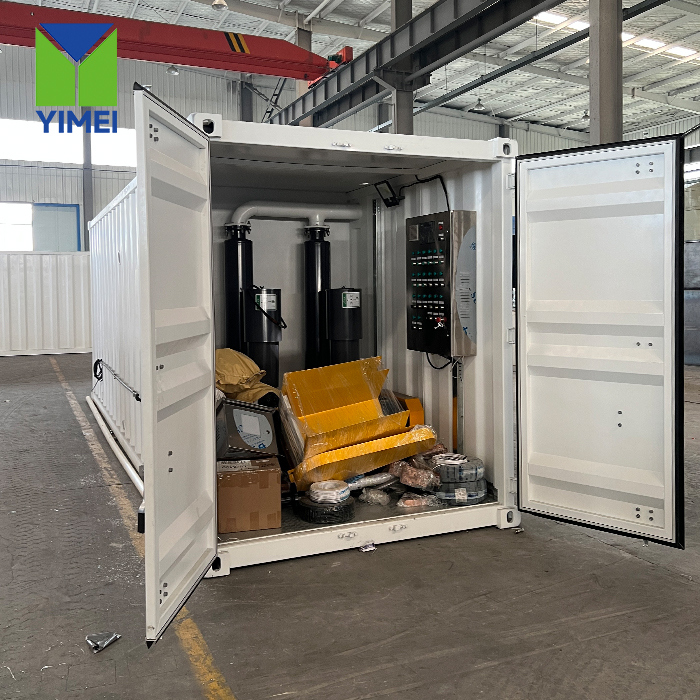
Ultimately, the choice of biological treatment technology acts as the primary lever for minimizing a facility's footprint. While various processes can achieve identical effluent quality, they do so using drastically different spatial configurations. By comparing the dominant treatment technologies in the industry, planners can evaluate the inherent trade-offs between spatial efficiency, operational complexity, and overall capital investment.
The Extended aeration packaged sewage treatment plant serves as the conventional baseline for decentralized wastewater management. This traditional process breaks down organic matter through prolonged aeration times, which is then followed by gravity settling within a distinct clarifier unit. Generally, it operates at a relatively low Mixed Liquor Suspended Solids (MLSS) concentration, typically hovering between 2,000 and 3,000 mg/L.
Since this method relies exclusively on suspended biological growth and natural gravity separation, it naturally demands the largest physical footprint. To accommodate the necessary liquid volumes for extended periods—often requiring 18 to 24 hours of retention time—the aeration basins must be exceptionally large. Additionally, the secondary clarifier needs substantial surface area to guarantee adequate sludge settling in compliance with strict surface overflow rates. Despite being the most land-intensive option, this technology boasts simpler daily operations, lower mechanical complexity, and reduced ongoing maintenance. As a result, it remains highly favorable for rural developments or industrial sites where land availability is plentiful.
The MBBR sewage treatment plant introduces specialized, suspended plastic media carriers directly into the aeration basin. These carriers supply thousands of square meters of protected surface area, creating an ideal environment for robust biological growth. By cultivating a highly active, dense biofilm on these moving carriers, the system is capable of processing heavier organic loads using a fraction of the water volume.
Consequently, this advanced technology sharply reduces the necessary size of the aeration tank when compared to standard extended aeration. Thanks to the significantly higher effective biomass concentration, engineers can often reduce the biological reactor's footprint by 30% to 40%. It is worth noting that an MBBR setup still requires retention screens to keep the media safely inside the reactor, along with a downstream clarifier or dissolved air flotation (DAF) unit to separate sloughed biofilm from the final effluent. Ultimately, MBBR represents an excellent middle-ground solution, perfectly balancing significant footprint reductions with manageable daily operational complexity.
For sites facing severe space constraints, the MBR packaged sewage treatment plant stands out as the ultimate solution. This cutting-edge technology submerges ultrafiltration or microfiltration membranes directly into the biological reactor. Acting as an absolute physical barrier, these membranes draw clean water through microscopic pores while effectively retaining all active biomass and suspended solids.
Because it leverages membrane filtration, MBR technology completely eliminates the need for bulky secondary clarifiers and tertiary sand filters. This streamlined consolidation yields an ultra-compact footprint, frequently requiring only half the land area of a conventional setup. Furthermore, MBR systems operate at much higher MLSS concentrations—typically between 8,000 and 12,000 mg/L—which shrinks the required tank volume even further. However, this spatial efficiency comes with trade-offs: higher energy consumption for membrane air scouring, the necessity of chemical clean-in-place (CIP) tanks (which slightly increase the footprint), and the mandatory requirement for strict overhead clearances to safely hoist and remove membrane cassettes during maintenance.
To precisely assess how these distinct technologies will impact spatial planning, engineers generally follow a standard sequence of calculations:
Calculate the baseline biological volume needed to handle the specific BOD load, utilizing standard kinetic modeling.
Establish the necessary clarifier surface area, dictated by peak hourly flows and maximum allowable overflow rates.
Evaluate the available vertical clearance required for pulling membranes, accessing media retention screens, or servicing clarifier skimmer mechanisms.
Outline the physical footprint for any necessary tertiary filtration and disinfection units when utilizing non-membrane processes.
Determine the dedicated space needed for chemical storage and dosing skids tailored to the selected treatment technology.
Technology Type | Relative Footprint | Typical MLSS Concentration | Clarifier Required? | Ideal Application Scenario |
|---|---|---|---|---|
Extended Aeration | Large (100% baseline) | 2,000 - 3,000 mg/L | Yes (Requires large surface area) | Rural developments, sites with abundant land, and low-complexity operations. |
MBBR (Moving Bed Biofilm Reactor) | Medium (60-70% of baseline) | Effective equivalent of 4,000+ mg/L | Yes (Standard clarifier or DAF) | Upgrades to existing infrastructure and projects with moderate space constraints. |
MBR (Membrane Bioreactor) | Ultra-Compact (40-50% of baseline) | 8,000 - 12,000 mg/L | No (Membranes act as the barrier) | Urban sites, strict effluent limits, and locations with severe spatial limits. |
When property lines or existing infrastructure strictly limit the available horizontal footprint, design engineers have to look upward. Utilizing multi-level designs and stacked treatment units enables the deployment of high-capacity systems within incredibly tight areas by maximizing vertical space. Typically, this strategic approach involves mounting lighter auxiliary equipment—such as air blowers, electrical control panels, and chemical dosing skids—onto elevated structural steel platforms positioned directly over the primary treatment tanks.
However, successfully implementing a vertical configuration demands rigorous structural engineering. The primary tanks' load-bearing walls must be engineered to withstand the dynamic vibrations generated by heavy blowers, alongside the static weight of full chemical totes. Safety is also paramount; elevated maintenance platforms require OSHA-compliant stairways, non-slip fiberglass grating, and robust safety rails, all of which slightly alter the spatial envelope. Furthermore, designers must properly size the influent pumps to overcome the increased vertical head required to push raw wastewater up to elevated pre-treatment screens at the pinnacle of the stacked layout.
Burying the treatment facility offers a highly compelling spatial advantage. Opting for a below-ground installation allows property developers to reclaim valuable surface area, repurposing it for parking lots, access roads, or aesthetic landscaping. Because the biological treatment processes occur entirely out of sight, this approach effectively minimizes noise and eliminates visual impact concerns for neighboring residents.
Despite these benefits, below-ground placement introduces complex civil engineering challenges that heavily influence the temporary construction footprint. Even though it preserves permanent surface space, the installation demands a significantly larger excavation area. To safely execute the dig, contractors must utilize heavy shoring or large trench boxes to stabilize the excavation walls. In areas with high groundwater tables, engineers must design massive, poured-in-place concrete ballast pads and anti-flotation collars; otherwise, buoyancy could literally push empty tanks out of the ground. Finally, designers still need to reserve specific surface areas for heavy-duty, H-20 traffic-rated access hatches. These hatches ensure operators can safely access the subterranean vaults for routine maintenance without completely disrupting surface operations.
Treatment facilities designed for low-flow applications—such as RV parks, rural gas stations, or boutique resorts—generally rely on single-tank or skid-mounted configurations. A standard package system processing under 10,000 GPD will typically fit neatly onto a single steel skid, roughly measuring 8 feet wide by 20 to 30 feet long. Conveniently, these compact dimensions allow the fully assembled unit to be shipped on a standard flatbed trailer, sidestepping the need for costly wide-load transport permits. Because of their highly consolidated nature, these systems require minimal site preparation, which is usually limited to pouring a single reinforced concrete pad and installing basic utility stub-outs.
When flow rates scale up to support decentralized communities of 500 to 2,500 people, footprint expectations shift drastically. Logistical shipping constraints naturally cap the maximum dimensions of a single factory-built tank at approximately 12 feet wide by 40 to 50 feet long. Consequently, once a facility's required capacity exceeds 50,000 GPD, design engineers must pivot from compact, single-skid units to complex, multi-tank configurations.
Deploying multiple parallel tanks increases the site's overall footprint exponentially. Because planners cannot position large tanks perfectly flush against one another, they must leave three to five feet of clearance between each vessel. This critical spacing accommodates bulky interconnecting flanged piping, large isolation valves, and safe walkways for plant operators. Ultimately, a 100,000 GPD system might demand three or four massive tanks, quickly transforming a straightforward concrete pad into a sprawling, multi-lane structural foundation that dictates the entire site layout.
Wastewater generation is rarely a steady, consistent stream. Standard morning and evening usage spikes generate diurnal peak flows that can easily overwhelm sensitive biological processes and wash out clarifiers. To safeguard the treatment system, engineers integrate equalization (EQ) tanks into the design. These essential tanks capture sudden influxes of wastewater and, utilizing forward flow pumps, dose it evenly into the treatment plant over a steady 24-hour cycle. Depending on the specific peaking factor—which is frequently 3.0 to 4.0 times the average daily flow—an EQ tank typically needs to hold between 25% and 30% of the total daily volume. Introducing an EQ tank substantially expands the facility's overall physical footprint, as it demands its own dedicated excavation zone or a separately poured concrete pad.
All active biological treatment processes continuously generate waste activated sludge. One of the most common spatial planning failures is severely underestimating the infrastructure required to safely manage this unavoidable byproduct. To prevent septic conditions and actively reduce sludge volume, facilities must incorporate dedicated aerobic digesters or aerated sludge holding tanks. Furthermore, if the site incorporates mechanical dewatering equipment—such as a centrifuge, screw press, or filter press—planners must proactively allocate space not only for the machinery itself but also for polymer makeup units and the heavy-duty roll-off dumpsters required to haul the dried biosolid cake away.
It is crucial to remember that a wastewater treatment plant is an active industrial environment requiring reliable, continuous access for heavy vehicles. Failing to map out logistics for large vacuum trucks is a critical design error. Because sludge holding tanks require periodic pump-outs, the site must accommodate massive vacuum trucks that demand exceptionally wide turning radiuses. Planners should design access routes capable of handling an AASHTO WB-50 design vehicle, ensuring a minimum 45-foot turning radius for safe maneuverability. Additionally, if the plant employs heavy submersible pumps or delicate MBR technology, the site must feature a clear, stable 20-foot by 20-foot ground staging area to support the outriggers of a boom crane needed to safely lift heavy equipment out of the basins.
Decentralized developments frequently scale in distinct phases over several years. Designing a site layout tailored strictly to current flow rates is a short-sighted approach that will inevitably trigger severe bottlenecks as the community expands. Intelligent site planning requires structuring the initial footprint to easily accommodate future modular add-ons. This forward-thinking strategy might involve pouring extended concrete pads during phase one, installing capped piping stub-outs for parallel treatment trains down the line, and purposefully oversizing both the headworks and EQ tanks to manage the ultimate build-out capacity from day one. Reserving this critical space early on saves developers from the immense cost of entirely relocating the facility in the future.
Conduct a highly detailed site survey to accurately map all property lines, existing utility corridors, and topographical constraints long before selecting any physical equipment.
Engage with local environmental regulatory agencies early on to pinpoint the exact setback mandates and buffer zones required for wastewater infrastructure within your specific zoning district.
Request precise 3D dimensional drawings and footprint specifications from your equipment manufacturers, ensuring they are based directly on your project's unique daily flow and peak organic loading factors.
Carefully calculate the necessary turning radiuses and overhead clearances required to accommodate heavy vacuum trucks and maintenance cranes, seamlessly integrating these dimensions into the final site layout.
Architect the initial site plan with dedicated physical reserves and capped utility stub-outs, guaranteeing seamless modular expansion as the facility's capacity demands grow over time.
A: Most standard regulatory guidelines establish a baseline minimum liquid capacity of 750 gallons for small-scale residential or commercial applications. As the system scales up to serve decentralized populations of around 2,500 people, this required capacity increases proportionately, driven by daily per capita flow estimates and specific organic loading metrics.
A: The allowable distance is heavily dictated by state-specific regulatory setbacks and mandated odor buffer zones. To effectively mitigate sanitary risks, noise, and odors, local environmental codes frequently enforce minimum separation distances ranging anywhere from 50 to 150 feet away from active water wells, property boundaries, and occupied buildings.
A: Yes, burying the plant successfully reclaims premium surface area for aesthetic landscaping or parking lots. However, developers must account for a significantly larger temporary construction footprint. Below-ground installations require extensive excavation, heavy shoring, anti-buoyancy concrete ballast pads, and dedicated surface clearances for heavy-duty access hatches.
A: Membrane Bioreactor (MBR) technology is widely recognized as requiring the smallest spatial footprint. By employing directly submerged ultrafiltration membranes, MBR systems entirely bypass the need for bulky secondary clarifiers and tertiary sand filters, resulting in an exceptionally compact facility layout.
A: A treatment site demands substantial clearance to accommodate heavy industrial vehicles. Large vacuum trucks require up to a 45-foot turning radius to safely pump out sludge tanks. Furthermore, the layout must provide secure ground staging and unobstructed overhead clearance for boom cranes to extract heavy submersible pumps or delicate membrane cassettes.
A: Absolutely. For plants processing more than 40,000 GPD or those operating without primary treatment, state criteria frequently mandate the installation of mechanical screens or comminutors. Planners must also carve out dedicated spatial footprints for blowers, chemical dosing skids, and—if local air quality regulations dictate—external odor control biofilters.


